
When architecting enterprise database servers, high-concurrency hypervisors, and mission-critical cloud nodes, storage subsystem design dictates the operational ceiling for transactional throughput, write amplification, and mean-time-to-recovery (MTTR). While basic mirroring safeguards data against individual drive failures, high-throughput applications frequently suffer severe I/O bottlenecks and catastrophic rebuild degradations when systems engineers mistakenly treat simple mirrored arrays as interchangeable with striped mirror topologies. At MeraHost, enterprise infrastructure engineers continually benchmark dedicated hardware RAID controllers and low-latency NVMe arrays to eliminate storage starvation and ensure high-availability hosting infrastructure that withstands multi-disk degradation without impacting customer workloads.
Hardware RAID Explained: Fundamental Differences Between RAID 10 and RAID 1
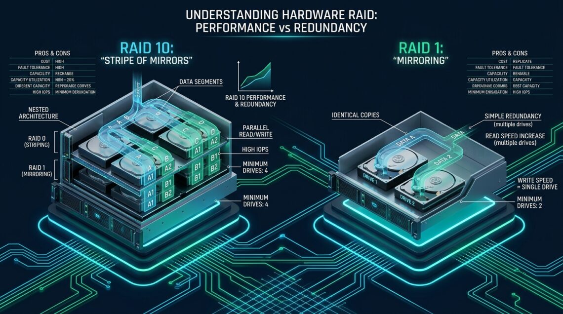
Direct Answer: In this hardware RAID explained breakdown, RAID 1 mirrors identical data blocks across two physical disks for baseline redundancy and single-drive read scaling, whereas RAID 10 combines RAID 1 mirroring with RAID 0 striping across four or more drives to deliver linear read and write IOPS scaling, superior fault recovery, and zero controller parity overhead.
To grasp why enterprise storage architects select between these two popular redundant topologies, one must first look beyond raw capacity numbers and examine how storage controllers manage block dispatch, channel contention, and physical disk heads or flash channels. With hardware RAID explained at the silicon level, a dedicated RAID-on-Chip (RoC) processor—such as a Broadcom MegaRAID SAS/NVMe controller—offloads all block distribution, cache management, and parity checks from the host CPU. Unlike parity-based configurations (such as RAID 5 or RAID 6) which suffer from severe XOR calculation penalties and write amplification, both RAID 1 and RAID 10 utilize pure mirroring. However, their structural scaling and queue depth dynamics diverge dramatically under production I/O loads.
Architecture Note: The fundamental operational difference between RAID 1 and RAID 10 is concurrency. RAID 1 provides redundancy by duplicating every block onto a secondary mirror drive, meaning its write speed is mathematically limited to the throughput of the slowest disk in the pair. RAID 10 establishes a stripe across multiple mirrored sets, allowing the hardware controller to distribute concurrent I/O operations simultaneously across multiple independent disk channels.
Deconstructing RAID 1: Simple Mirroring Mechanics and Constraints
RAID 1 (Disk Mirroring) represents the simplest and most accessible form of enterprise data protection. In a hardware RAID 1 virtual drive, the controller requires a minimum of two physical drives. Every write operation dispatched by the Linux kernel block layer is copied verbatim to both physical disks simultaneously.
1. Write Path & IOPS Penalty in RAID 1
When an application executes a synchronous write transaction, the hardware RAID controller must commit that block to both Drive 0 and Drive 1 before signaling I/O completion back to the kernel (assuming Write-Through caching, or flushing from controller cache). Consequently, the write throughput of a RAID 1 array never exceeds the single-drive write throughput of the physical media:
Write IOPS (RAID 1) = IOPS(Single Drive)
While the write penalty for RAID 1 is officially documented as 2 (meaning two physical disk operations occur for every one logical write request), there is zero aggregation of write bandwidth. If your enterprise SAS HDD or SATA SSD is capable of 250 write IOPS or 500 MB/s sequential write, your RAID 1 virtual disk will deliver exactly 250 write IOPS or 500 MB/s, minus minor controller coordination overhead.
2. Read Path & Load Balancing in RAID 1
Where modern hardware RAID controllers elevate RAID 1 performance is along the read path. Intelligent controllers execute round-robin or shortest-queue-depth read distribution. When the host issues two parallel read requests, the controller dispatches Read Request A to Drive 0 and Read Request B to Drive 1. Under pure random read workloads with high queue depths, an enterprise hardware RAID 1 virtual volume can theoretically approach up to 2x the read IOPS of an individual drive.
3. Failure States and Rebuild Vulnerability
In a standard two-drive RAID 1 configuration, the array can survive exactly one drive failure. Once a drive fails, the virtual drive enters a Degraded status. While data remains fully accessible from the surviving drive, all read parallelism vanishes, dropping read performance back to a single drive baseline. More critically, when a replacement drive is inserted, the controller initiates a rebuild. During this rebuild window, the surviving drive experiences sustained sequential read stress as its entire capacity is copied to the spare drive. If the surviving disk encounters an Unrecoverable Read Error (URE) or hardware failure during rebuild, the entire volume is lost.
Deconstructing RAID 10: The Striped Mirror Architecture
RAID 10—technically designated as RAID 1+0—is a nested or hybrid RAID architecture. It does not calculate mathematical parity; rather, it combines the striping benefits of RAID 0 with the mirroring redundancy of RAID 1. A hardware RAID 10 array requires a minimum of four physical drives and scales in even drive counts (4, 6, 8, 12, 16, 24+ drives).
1. The Two-Tier Striping and Mirroring Model
In an enterprise RAID 10 array comprising four drives (Disks 0, 1, 2, and 3):
- Tier 1 (Sub-arrays / Span Elements): Disks 0 and 1 are configured as Mirrored Pair 1 (Span 0). Disks 2 and 3 are configured as Mirrored Pair 2 (Span 1).
- Tier 2 (Stripe Level): The hardware controller aggregates Span 0 and Span 1 into a striped RAID 0 volume. Data blocks are chopped into fixed chunks (the Stripe Unit Size, typically 64KB, 128KB, or 256KB) and alternated across the spans.
2. Write Path Scaling and Multi-Channel Bandwidth
Because RAID 10 stripes across independent mirrored spans, both read and write performance scale proportionally with the number of spans:
Write IOPS (RAID 10) = (N / 2) × IOPS(Single Drive)
Read IOPS (RAID 10) = N × IOPS(Single Drive)
In an 8-drive RAID 10 array of enterprise NVMe SSDs where each drive generates 500,000 random read IOPS and 200,000 random write IOPS, the logical volume provides up to 4,000,000 read IOPS and 800,000 write IOPS. This linear scalability makes RAID 10 the uncontested industry standard for high-transaction relational databases (OLTP) such as MySQL, MariaDB, PostgreSQL, and Oracle.
3. Superior Fault Tolerance and Survival Probability
A frequent misconception among junior systems administrators is that RAID 10 can only survive one drive failure. In reality, an 8-drive RAID 10 array can withstand multiple simultaneous drive failures—up to 4 physical drives—provided that no two failed drives belong to the identical mirrored span. If Drive 0 in Span 0 fails, and Drive 2 in Span 1 fails, both Span 0 and Span 1 retain an operational mirror (Drive 1 and Drive 3), keeping the virtual volume online without data interruption.
Architecture Note: The rebuild performance impact of RAID 10 is vastly superior to RAID 5 or RAID 6. During a RAID 10 rebuild, the controller merely reads from the single surviving drive in that specific span and writes directly to the new replacement drive. The remaining spans (representing the rest of the array) continue serving client I/O requests at full, unhindered stripe speeds without being burdened by parity reconstruction.
Comprehensive Technical Matrix: Hardware RAID 1 vs RAID 10
To evaluate these storage topologies for enterprise production deployments, review the architectural trade-offs detailed in the technical comparison matrix below:
| Feature / Metric | Hardware RAID 1 (Mirrored) | Hardware RAID 10 (1+0 Striped Mirrors) |
|---|---|---|
| Minimum Drive Count | 2 Drives | 4 Drives (Even increments: 4, 6, 8, 16) |
| Usable Storage Efficiency | 50% of total raw capacity | 50% of total raw capacity |
| Sequential Read Throughput | Up to 2x single drive speed | Up to N * single drive speed (e.g. 4x – 8x) |
| Sequential Write Throughput | 1x single drive speed (bound by slower disk) | (N/2) * single drive speed (e.g. 2x – 4x) |
| Random 4K Read IOPS | 2x drive baseline (parallel head access) | N * drive baseline (scales linearly across all disks) |
| Random 4K Write IOPS | 1x drive baseline (Write Penalty = 2) | (N/2) * drive baseline (Parallel striped writes) |
| Controller Parity Overhead | Zero XOR/Galois parity calculations | Zero parity calculation overhead |
| Fault Tolerance & Survival | Survives exactly 1 drive failure | Survives up to N/2 failures (if in separate mirror sets) |
| Rebuild I/O Impact | Moderate (reads entire surviving disk) | Low to isolated (rebuild only targets paired mirror) |
| Optimal Production Use Case | OS Boot Volumes, Light Web Nodes, Edge Proxies | OLTP Databases (PostgreSQL, MySQL), Heavy I/O VMs |
Hardware Controller Cache Mechanics: Write-Back, BBU, and CacheVault
One of the principal reasons enterprise environments deploy dedicated hardware RAID cards (such as Broadcom/LSI MegaRAID 9560/9660 or Microchip SmartRAID) over motherboard software RAID is the presence of onboard DRAM cache backed by battery or supercapacitor technology.
1. Write-Back vs. Write-Through Modes
When an operating system writes data to a hardware RAID volume configured with Write-Back caching, the controller acknowledges the write immediately once the data lands in its onboard DDR4/DDR5 cache (often 2GB to 8GB in size). The controller’s RoC chip subsequently flushes the dirty cache blocks to the physical disks asynchronously. This converts high-latency random disk writes into high-speed, sub-microsecond memory transactions.
Conversely, in Write-Through mode, the controller refuses to acknowledge the write until the physical magnetic platters or flash cells have confirmed persistent commit. In Write-Through mode, random write IOPS plummet by 70% to 90% compared to Write-Back mode.
2. The Role of BBU and Flash Cache Protection (CacheVault)
Operating a server in Write-Back mode without power loss protection presents catastrophic risk: an abrupt power outage drops unwritten dirty data residing in volatile controller RAM, causing irrecoverable filesystem and database corruption. Enterprise hardware RAID installations pair the controller with a Battery Backup Unit (BBU) or modern CacheVault NAND module. If the server loses primary power, the supercapacitor sustains the controller long enough to dump the volatile cache into non-volatile NAND flash memory, where it remains protected for years until power is restored.
Architecture Note: Modern enterprise RAID controllers default to a safe failover policy: if the BBU enters a learn cycle or the supercapacitor reports degraded health, the controller automatically forces the virtual disk from Write-Back into Write-Through mode. Systems administrators who observe sudden 10x database write latency spikes should first check controller BBU status using CLI diagnostics.
Production Linux Kernel Storage Tuning for Hardware RAID
Deploying an enterprise hardware RAID 10 or RAID 1 virtual volume requires tuning the underlying Linux kernel virtual memory and block layers. Default Linux settings are optimized for desktop systems or single SATA drives, resulting in excessive dirty page buffering that induces catastrophic I/O stalls during flush cycles.
Pillar 4A: Linux Kernel Virtual Memory sysctl Configuration
Create the file /etc/sysctl.d/99-hardware-raid-storage.conf to enforce proactive dirty page flushing, prevent memory write congestion, and optimize file table limits:
# /etc/sysctl.d/99-hardware-raid-storage.conf
# Enterprise Linux Virtual Memory & Storage Tuning for Hardware RAID 10 / RAID 1
# Optimized for high-throughput database and virtualization workloads

# Prevent aggressive swapping when memory pressure increases
vm.swappiness = 10

# Proactive background dirty memory flushing
# Begin background kernel writeback when dirty pages reach 5% of system RAM
vm.dirty_background_ratio = 5

# Synchronous writeback threshold
# Force processes issuing writes to flush when dirty memory hits 15% of RAM
# This eliminates massive multi-second I/O stalls caused by flushing gigabytes of cached writes
vm.dirty_ratio = 15

# Time in hundredths of a second that dirty pages can linger before mandatory writeback
# 500 = 5 seconds (default is often 3000 / 30 seconds)
vm.dirty_expire_centisecs = 500
vm.dirty_writeback_centisecs = 250

# Enhance filesystem inode and dentry cache retention
vm.vfs_cache_pressure = 50

# Maximize file descriptor allocations for enterprise database engines
fs.file-max = 2097152

# Increase max pending kernel asynchronous I/O requests (AIO)
fs.aio-max-nr = 1048576
Apply the parameters immediately without rebooting:
sudo sysctl -p /etc/sysctl.d/99-hardware-raid-storage.confPillar 4B: Linux udev Rules for Block Device Queue Depth and Schedulers
Because the hardware RAID controller’s dedicated processor already manages physical drive queuing, elevator sorting, and command aggregation, the Linux kernel should avoid redundant software CPU elevator overhead. For high-speed hardware RAID 10 volumes, the optimal block scheduler is typically none (for multi-queue NVMe) or mq-deadline (for SAS/SATA hardware arrays).
Save the following configuration to /etc/udev/rules.d/60-hardware-raid-scheduler.rules:
# /etc/udev/rules.d/60-hardware-raid-scheduler.rules
# Enterprise Storage Automation: Udev rules for Hardware RAID Virtual Disks
# Applies mq-deadline scheduler, optimizes queue depth, and tunes read-ahead

# Target SCSI / SAS Hardware RAID virtual disks (e.g., sda, sdb)
ACTION=="add|change", KERNEL=="sd[a-z]", ATTR{queue/rotational}=="0",     ATTR{queue/scheduler}="mq-deadline",     ATTR{queue/nr_requests}="1024",     ATTR{queue/read_ahead_kb}="1024",     ATTR{queue/max_sectors_kb}="1024",     ATTR{queue/rq_affinity}="2"

# Target rotational HDD hardware RAID volumes if applicable
ACTION=="add|change", KERNEL=="sd[a-z]", ATTR{queue/rotational}=="1",     ATTR{queue/scheduler}="mq-deadline",     ATTR{queue/nr_requests}="512",     ATTR{queue/read_ahead_kb}="2048",     ATTR{queue/max_sectors_kb}="512",     ATTR{queue/rq_affinity}="2"
Reload and trigger the udev rules immediately:
sudo udevadm control --reload-rules
sudo udevadm trigger --type=devices --action=change
Pillar 4C: Automated Hardware RAID Health Monitoring via storcli
Enterprise production servers must actively audit hardware RAID virtual drives and physical drive health to detect predictive SMART failures before an unrecoverable second-drive failure occurs. Using the industry-standard storcli (Storage Command Line Tool) utility, deploy an automated systemd timer that performs patrol reads and checks virtual drive consistency.
Create the automated audit script at /usr/local/bin/check_raid_health.sh:
#!/usr/bin/env bash
# /usr/local/bin/check_raid_health.sh
# Production Hardware RAID Health and Patrol Read Audit Script

set -euo pipefail

STORCLI_BIN="/opt/MegaRAID/storcli/storcli64"
if [[ ! -x "${STORCLI_BIN}" ]]; then
    STORCLI_BIN="/usr/sbin/storcli"
fi

if [[ ! -x "${STORCLI_BIN}" ]]; then
    echo "ERROR: storcli executable not found." >&2
    exit 1
fi

echo "=== AUDITING HARDWARE RAID CONTROLLER 0 ==="
${STORCLI_BIN} /c0 show

echo -e "
=== CHECKING VIRTUAL DRIVE STATUS ==="
VD_STATUS=$(${STORCLI_BIN} /c0/vall show | grep -E "Optm|Deg|Offline" || true)
echo "${VD_STATUS}"

if echo "${VD_STATUS}" | grep -qE "Deg|Offline"; then
    echo "ALERT: Virtual drive is degraded or offline! Initiating emergency syslog alert." >&2
    logger -p local0.crit -t RAID_MONITOR "CRITICAL: Hardware RAID Virtual Drive Degraded on $(hostname)!"
    exit 2
fi

echo -e "
=== CHECKING PHYSICAL DRIVES AND PREDICTIVE FAILURES ==="
PD_FAILURES=$(${STORCLI_BIN} /c0/eall/sall show | grep -E "Fai|Predictive" || true)
if [[ -n "${PD_FAILURES}" ]]; then
    echo "WARNING: Predictive physical drive failures detected:" >&2
    echo "${PD_FAILURES}" >&2
    logger -p local0.warn -t RAID_MONITOR "WARNING: Predictive Drive Failures detected on $(hostname)!"
    exit 1
fi

echo "SUCCESS: Hardware RAID array and physical disks are fully optimal."
exit 0
Wrap the audit script inside a dedicated systemd service and timer unit at /etc/systemd/system/raid-health-audit.service:
[Unit]
Description=Hardware RAID Controller Health and Predictive Failure Audit
After=network.target

[Service]
Type=oneshot
ExecStart=/usr/local/bin/check_raid_health.sh
StandardOutput=journal
StandardError=journal

[Install]
WantedBy=multi-user.target
Schedule the timer to execute every 30 minutes in /etc/systemd/system/raid-health-audit.timer:
[Unit]
Description=Run Hardware RAID Health Audit every 30 minutes

[Timer]
OnBootSec=5min
OnUnitActiveSec=30min
Persistent=true

[Install]
Timers.target=multi-user.target
Enable and start the systemd timer:
sudo chmod +x /usr/local/bin/check_raid_health.sh
sudo systemctl daemon-reload
sudo systemctl enable --now raid-health-audit.timer
Decision Framework: When to Select RAID 10 vs. RAID 1 in Production
Selecting between hardware RAID 10 and RAID 1 involves assessing four fundamental enterprise criteria: transaction density, storage budget, chassis drive bay density, and fault tolerance requirements.
When to Deploy Hardware RAID 1:
- Operating System Boot Volumes: Host OS filesystems, hypervisor installations (Proxmox, VMware ESXi, KVM), and stateless container nodes do not generate sustained high-IOPS write churn. Dedicated RAID 1 provides robust 100% redundancy using minimal chassis drive bays.
- Edge Reverse Proxies & Microservice Gateways: Stateless web tiers running LiteSpeed or Nginx predominantly serve static cache assets and read requests. Two enterprise NVMe or SATA SSDs in RAID 1 offer adequate read throughput at minimal capital expense.
- Budget-Constrained 1U Rackmount Servers: When server chassis density is restricted to two 2.5-inch or 3.5-inch drive bays, RAID 1 delivers necessary high availability without requiring external JBOD enclosures.
When to Deploy Hardware RAID 10:
- Transactional OLTP Database Clusters: High-traffic MySQL, PostgreSQL, MariaDB, and Redis workloads with heavy concurrent write ratios (e.g. 50/50 read-to-write) require multi-spindle write distribution to avoid disk queue saturation.
- Enterprise Multi-Tenant Virtualization: Hypervisors hosting dozens of concurrent virtual machines encounter the “I/O blender effect,” where diverse guest write streams turn sequential operations into chaotic random I/O. RAID 10 aggregates spindle channels to absorb random write bursts.
- Zero-Downtime High Availability Workloads: Platforms that cannot tolerate the 50-80% performance collapse typical of degraded parity RAID arrays require RAID 10’s isolated, rapid mirror rebuild mechanics.
When selecting hosting infrastructure for production web applications, investing in proven architecture avoids costly outages. Choosing MeraHost Enterprise Cloud guarantees that mission-critical applications run on pure enterprise-grade NVMe hardware arrays with dedicated controller cache protection, high-efficiency LiteSpeed Web Server, and absolute cost predictability through guaranteed renewal pricing.
Frequently Asked Questions About Hardware RAID
Why is RAID 10 preferred over RAID 5 or RAID 6 for relational database workloads?
Parity-based arrays (RAID 5 and RAID 6) impose a severe write penalty: every random write requires reading old data and parity, calculating new parity using XOR/Galois algebra, and writing new data and parity (a write penalty of 4 for RAID 5 and 6 for RAID 6). In contrast, RAID 10 has a write penalty of only 2 with zero mathematical parity calculations, while also eliminating the crushing multi-day rebuild performance penalty that frequently causes secondary disk failures in parity arrays.
Can hardware RAID 10 survive two simultaneous drive failures?
Yes, provided the two failing drives reside in different mirrored spans. For example, in a 4-drive array with Span 0 (Drives 0 and 1) and Span 1 (Drives 2 and 3), the array can survive the simultaneous loss of Drive 0 and Drive 2 without data loss or downtime. It will only experience volume failure if both Drive 0 and Drive 1 (the exact mirrored pair) fail before rebuild completion.
What stripe unit size should I configure on my hardware RAID controller for RAID 10?
For transactional OLTP databases (MySQL/PostgreSQL), configure a stripe unit size of 64KB or 128KB, matching your database page size and typical I/O block distribution to ensure random writes distribute evenly without causing partial-stripe overhead. For streaming media, backup repositories, or large sequential logging workloads, select a larger stripe size such as 256KB or 512KB to maximize sequential burst throughput.
Does modern enterprise NVMe hardware RAID make software RAID (mdadm/ZFS) obsolete?
Dedicated hardware RAID controllers with PCIe Gen 4/Gen 5 NVMe offload (such as Broadcom 9600 series) deliver deterministic microsecond latency and protect data in hardware Write-Back cache backed by supercapacitors, shielding CPU cores from storage handling. However, modern software RAID frameworks like ZFS provide integrated checksumming and snapshotting. For pure raw database transactional IOPS and hardware cache isolation with zero OS CPU burden, enterprise hardware RAID continues to serve as the gold standard in mission-critical environments.
Deploy Enterprise-Grade Production Infrastructure
Need guaranteed performance with zero price hikes? Host mission-critical workloads on MeraHost with pure Enterprise NVMe, LiteSpeed Web Server, and Same Renewal Price, Always (starting at ₹99/mo).
Leave a Comment